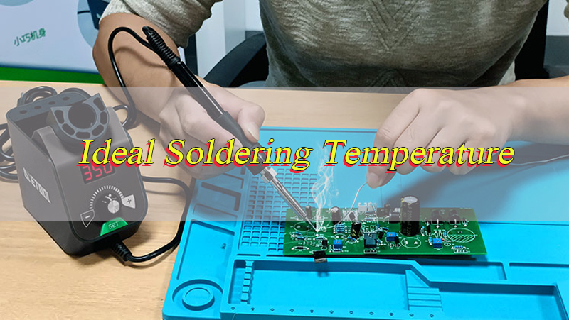
What is the ideal soldering temperature for circuit boards, and why does this value vary across projects? The ideal soldering temperature is not a fixed number but a calibrated range that balances solder melting, component safety, and joint reliability.
For most standard circuit boards, the ideal soldering temperature falls between 250°C and 300°C for manual soldering, while reflow processes use 210°C to 260°C based on solder type. This range ensures proper wetting of copper pads, activates flux effectively, and avoids thermal damage to sensitive components. Understanding this core range is critical for engineers to produce consistent, high-quality solder joints and avoid common defects like cold joints or lifted pads.
Is There a Universal Ideal Soldering Temperature for All Circuit Boards?
No, there is no universal ideal soldering temperature that works for all circuit boards, as the optimal range depends on three core variables: solder alloy type, assembly method, and component thermal tolerance. A one-size-fits-all temperature setting will either fail to melt solder fully or damage delicate parts, making tailored settings mandatory for every project. Even identical board designs can require adjustments if components or solder types change, confirming the need for project-specific temperature calibration.
Key Variables That Eliminate a Universal Temperature:
- Solder Alloy Composition: Leaded and lead-free solders have distinct melting points, creating separate ideal temperature ranges.
- Assembly Method: SMT, through-hole, manual, and reflow soldering each demand unique temperature profiles.
- Component Sensitivity: Delicate parts like LEDs and fine-pitch ICs require lower temperatures than robust components like connectors.
- PCB Material: FR-4 and flexible boards have different thermal limits, altering safe temperature ranges.
What is the Ideal Soldering Temperature for Leaded Solder on Circuit Boards?
The ideal soldering temperature for leaded solder (typically Sn63/Pb37 eutectic alloy) on circuit boards is 300°C to 350°C for manual soldering and 210°C to 230°C for reflow soldering. Leaded solder melts at 183°C, so the ideal soldering temperature is set 120°C to 170°C above the melting point to ensure full wetting and flux activation without overheating. This range is forgiving, with a wide process window that tolerates minor temperature fluctuations, making it ideal for prototyping and low-volume production.
Leaded Solder Temperature Guidelines
- Manual Soldering Iron: 300°C–350°C (tip temperature), with 2–3 second contact time per joint.
- Reflow Soldering: Peak temperature 210°C–230°C, with 60–90 seconds above melting point.
- Wave Soldering: 230°C–250°C, ideal for through-hole components on mass-production boards.
What is the Ideal Soldering Temperature for Lead-free Solder on Circuit Boards?
The ideal soldering temperature for lead-free solder (commonly SAC305: Sn96.5/Ag3/Cu0.5) on circuit boards is 350°C to 400°C for manual soldering and 240°C to 250°C for reflow soldering. Lead-free solder melts at 217°C–227°C, requiring a higher ideal soldering temperature than leaded solder to overcome poorer wetting properties. This range has a narrower process window (only 15°C–20°C between success and failure), demanding precise temperature control to avoid component damage or incomplete joints.
Lead-Free Solder Temperature Guidelines
- Manual Soldering Iron: 350°C–380°C (tip temperature), with 3–4 second contact time per joint.
- Reflow Soldering: Peak temperature 240°C–250°C, with 50–70 seconds above melting point.
- Wave Soldering: 250°C–260°C, with titanium-lined pots to resist tin scavenging.
Does the Ideal Soldering Temperature Differ for SMT and Through-Hole Circuit Boards?
Yes, the ideal soldering temperature differs significantly for SMT and through-hole circuit boards due to differences in component size, pad design, and heat distribution. SMT components have small, low-mass pads that heat quickly, requiring lower ideal temperatures to avoid damage. Through-hole components have large leads and high-mass pads that act as heat sinks, demanding higher ideal temperatures to ensure solder flows through plated holes and forms strong joints.
SMT vs. Through-Hole Temperature Comparison
| Assembly Type | Ideal Manual Temperature | Ideal Reflow/Wave Temperature | Key Reason |
|---|---|---|---|
| SMT | 280°C–320°C | 220°C–240°C (reflow) | Small pads, delicate components |
| Through-Hole | 320°C–380°C | 250°C–280°C (wave) | Large leads, heat-sink pads |
SMT soldering relies on precise reflow profiles with slow ramp rates (1–3°C/s) to prevent component warping. Through-hole soldering uses higher temperatures to penetrate holes, with longer dwell times to ensure full solder coverage.
What Factors Affect the Ideal Soldering Temperature for Circuit Boards?
The ideal soldering temperature for circuit boards is shaped by six critical factors, each requiring careful evaluation to avoid defects. Ignoring any factor leads to poor joint quality or component damage, making systematic assessment essential for every project.
1. Solder Alloy Type
Leaded solders (183°C melting point) need lower ideal temperatures than lead-free solders (217°C–227°C melting point). Alloy variations like bismuth-doped lead-free solders lower melting points, adjusting the ideal range by 20°C–30°C.
2. PCB Material and Thickness
- FR-4: Most common, Tg 130°C–140°C; ideal peak temperature ≤250°C to avoid warping.
- Flexible Boards: Polyimide-based, lower thermal resistance; ideal temperature reduced by 30°C–50°C.
- Thickness: Boards >2mm or with 2oz+ copper layers need 10°C–20°C higher temperature to compensate for heat sinking.
3. Component Thermal Sensitivity
- Delicate Parts: LEDs, MLCCs, fine-pitch ICs (e.g., QFN, BGA) require 280°C–320°C ideal temperature.
- Robust Parts: Connectors, transformers, through-hole resistors tolerate 350°C–400°C.
- Critical Rule: Never exceed the component’s maximum rated temperature (typically 260°C for 10 seconds).
4. Soldering Method
- Manual: Iron tip temperature 300°C–400°C, adjusted by joint size.
- Reflow: Controlled profile with preheat (150°C–180°C), soak, and peak zones.
- Wave: Solder pot temperature 230°C–260°C, with board preheating to 100°C–150°C.
5. Flux Type and Activation
Flux activates at specific temperatures: no-clean flux at 150°C–180°C, water-soluble flux at 180°C–200°C. The ideal soldering temperature must align with flux activation to remove oxides and improve wetting.
6. Joint Size and Thermal Mass
Large joints (e.g., ground pads, power connectors) need higher ideal temperatures due to greater heat loss. Small joints (01005 SMDs) require lower temperatures to avoid overheating adjacent components.
What is the Ideal Soldering Temperature for Delicate Circuit Board Components?
The ideal soldering temperature for delicate circuit board components (including LEDs, MLCC capacitors, fine-pitch ICs, and small SMDs) is 280°C to 320°C for manual soldering and 220°C to 235°C for reflow soldering. This lower ideal soldering temperature prevents thermal shock, component cracking, or internal damage while still melting solder and activating flux. Delicate components have tight thermal margins, even 30 seconds at 350°C can cause permanent failure.
Critical Guidelines for Delicate Components
- Use Lead-Free Solder with Low Melting Point: SAC0307 or bismuth alloys (melting point 200°C–210°C) reduce required temperature.
- Short contact time: ≤2 seconds per joint to minimize heat exposure.
- Preheat the PCB: 100°C–120°C for 60 seconds to reduce thermal gradient.
- Use Fine-Tipped Irons: 0.5mm–1mm tips for precise heat application, avoiding adjacent components.
How to Determine the Ideal Soldering Temperature for Your Circuit Board Project?
Determining the ideal soldering temperature for your circuit board project requires a systematic, step-by-step process that balances all critical factors. This method ensures you select a temperature range that maximizes joint reliability while minimizing component risk.
Step 1: Identify Solder Alloy Specifications
Check the solder wire or paste datasheet for melting point and recommended temperature range. Note if it is leaded (183°C) or lead-free (217°C–227°C) as this sets the baseline ideal soldering temperature.
Step 2: Review PCB Material and Stackup
- Confirm substrate type (FR-4, polyimide, aluminum).
- Check thickness and copper weight (1oz, 2oz).
- Calculate thermal mass: thicker boards or heavy copper require +10°C to +20°C.
Step 3: Audit Component Thermal Ratings
- List all components and their maximum soldering temperature (from datasheets).
- The lowest component rating sets the upper limit for your ideal temperature.
- Flag delicate parts (LEDs, fine-pitch ICs) for reduced temperature settings.
Step 4: Select Assembly Method and Adjust
- Manual: Start at 320°C for leaded, 360°C for lead-free; adjust ±20°C based on joint size.
- Reflow: Program peak temperature 30°C–50°C above solder melting point; set ramp rate ≤2°C/s.
- Wave: Set pot temperature 240°C–250°C; preheat board to 120°C–150°C.
Step 5: Test and Validate with a Trial Run
Use a spare PCB with identical components for a test solder.
Inspect joints for:
- Good: Shiny, smooth, full wetting (ideal temperature achieved).
- Cold Joints: Dull, grainy (temperature too low).
- Bridging/Lifted Pads: Excess heat (temperature too high).
Adjust temperature by 10°C increments until optimal results are achieved.
What Happens If You Exceed the Ideal Soldering Temperature for Circuit Boards?
Exceeding the ideal soldering temperature for circuit boards causes severe, often irreversible damage to components, PCBs, and solder joints. The risks increase exponentially with temperature and exposure time, making strict adherence to the ideal range critical.
Key Consequences of Excessive Temperature
1. Component Damage:
- Delicate ICs suffer internal circuit damage or package cracking.
- Electrolytic capacitors bulge or leak due to electrolyte breakdown.
- LEDs experience brightness reduction or permanent failure from thermal stress.
2. PCB Degradation:
- FR-4 substrates warp or delaminate when Tg (130°C–140°C) is exceeded.
- Copper pads lift from the board, destroying electrical connections.
- Solder mask peels or discolors, exposing copper to oxidation.
3. Solder Joint Defects:
- Excessive intermetallic compound (IMC) growth (Cu6Sn5 → Cu3Sn) weakens joints, causing premature failure.
- Solder oxidizes rapidly, forming brittle, non-conductive joints.
- Solder balling occurs, creating short circuits between adjacent pads.
4. Reliability Issues:
- Overheated joints have reduced mechanical strength, failing under vibration or thermal cycling.
- Oxidized joints develop high resistance, leading to electrical failures over time.
What if the Soldering Temperature is Lower Than the Ideal Soldering Temperature for Circuit Boards?
Using a soldering temperature lower than the ideal soldering temperature results in incomplete solder melting, poor wetting, and weak, unreliable joints. While less immediately destructive than excessive heat, low temperature causes latent defects that lead to field failures and increased rework costs.
Key Consequences of Insufficient Temperature
Cold Solder Joints:
- Dull, grainy appearance with poor adhesion to pads and leads.
- Brittle joints that break easily under minor stress or vibration.
- High electrical resistance, causing signal loss or intermittent connections.
Incomplete Wetting:
- Solder beads up on pads instead of spreading, creating partial connections.
- Plated through-holes fail to fill, leaving voids that weaken joints.
- Flux activation is incomplete, leaving oxides on copper pads that corrode over time.
Rework and Yield Loss:
- Low-temperature joints require frequent rework, increasing labor costs.
- Unreliable joints lead to field failures, damaging product reputation.
- Inconsistent solder flow reduces production yield, wasting materials and time.
Is the Ideal Soldering Temperature the Same for FR-4 and Flexible Circuit Boards?
No, the ideal soldering temperature is not the same for FR-4 and flexible circuit boards due to differences in substrate material, thermal resistance, and mechanical flexibility. Flexible boards require a lower ideal soldering temperature to avoid damaging their delicate polyimide-based structure, while FR-4 can tolerate higher temperatures due to its rigid, heat-resistant composition.
FR-4 vs. Flexible Board Temperature Differences
| Board Type | Material | Ideal Manual Temperature | Ideal Reflow Temperature | Key Limitation |
|---|---|---|---|---|
| FR-4 | Epoxy-glass composite | 300°C–380°C | 220°C–250°C | Tg 130°C–140°C (warp risk above) |
| Flexible | Polyimide (PI) | 260°C–300°C | 200°C–220°C | Thin structure, low thermal resistance |
Flexible circuit boards are typically 0.1mm–0.2mm thick, making them prone to burning, warping, or delamination at temperatures above 300°C. Their copper traces are also thinner, increasing the risk of pad lifting at high heat. FR-4 boards (1mm–2mm thick) have better thermal stability, allowing use of the full ideal soldering temperature range for leaded and lead-free solders.
How to Adjust a Soldering Iron to Reach the Ideal Soldering Temperature for Circuit Boards?
Adjusting a soldering iron to reach the ideal soldering temperature for circuit boards requires precise calibration and technique, tailored to solder type, joint size, and component sensitivity. Proper adjustment ensures you hit the ideal temperature range consistently, avoiding defects and damage.
Step 1: Select the Right Iron and Tip
- Use a temperature-controlled soldering iron (40W–60W) for precise adjustment.
- Choose tip size: 0.5mm–1mm for small SMT joints, 2mm–3mm for through-hole joints.
- Ensure the tip is clean and tinned (coated with a thin layer of solder) for accurate heat transfer.
Step 2: Calibrate the Iron Temperature
1. Plug in the iron and turn it on; allow 5–10 minutes to reach stable temperature.
2. Use a temperature meter (contact or infrared) to measure the tip temperature.
3. Adjust the temperature dial up or down until the meter reads the target ideal temperature:
- Leaded solder: 300°C–350°C
- Lead-free solder: 350°C–380°C
- Delicate components: 280°C–320°C
4. Recheck the temperature after adjustment; repeat until stable.
Step 3: Optimize Technique for Ideal Heat Transfer
1. Tin the Tip: Apply a small amount of solder to the tip before soldering to improve thermal contact.
2. Heat Both Pad and Lead: Touch the iron tip to both the copper pad and component lead simultaneously for 1–2 seconds.
3. Apply Solder: Feed solder into the joint until it flows smoothly and covers the pad and lead.
4. Remove Iron Quickly: Pull the iron away once the joint is complete to avoid overheating.
Step 4: Adjust for Joint Size and Environment
- Large Joints: Increase temperature by 20°C–30°C or use a wider tip.
- Small Joints: Decrease temperature by 10°C–20°C and use a fine tip.
- Cold Environments: Increase temperature by 10°C–20°C to compensate for heat loss.
- Humid Conditions: Ensure the tip is clean and tinned to maintain heat transfer efficiency.
FAQs About Ideal Soldering Temperature
Q1: What is the ideal soldering temperature for mass production of circuit boards?
A1: The ideal soldering temperature for mass production uses reflow ovens with leaded solder at 210°C–230°C peak and lead-free solder at 240°C–250°C peak. This controlled profile ensures consistent joint quality across thousands of boards, with precise ramp and soak zones to minimize defects.
Q2: Can I use the same ideal soldering temperature for both prototyping and mass production?
A2: Prototyping often uses manual soldering with higher ideal temperatures (300°C–380°C), while mass production uses automated reflow with lower peak temperatures (210°C–250°C). Adjustments are needed due to differences in heat application speed and consistency between manual and automated processes.
Q3: How often should I recheck the ideal soldering temperature during a production run?
A3: Recheck the iron or oven temperature every 30 minutes during production, or after 50–100 joints. Temperature drift can occur due to tip wear, power fluctuations, or environmental changes, requiring minor adjustments to maintain the ideal range.
Q4: What is the ideal soldering temperature for aluminum-backed PCBs?
A4: Aluminum-backed PCBs require an ideal soldering temperature 20°C–40°C higher than standard FR-4 boards (340°C–400°C manual, 250°C–260°C reflow) due to aluminum’s high thermal conductivity, which dissipates heat quickly. Preheating the board to 150°C–180°C is critical to ensure proper solder flow.
Q5: Does the ideal soldering temperature change with solder wire diameter?
A5: Thicker solder wire (1.0mm–1.5mm) may require a 10°C–20°C higher ideal temperature to melt fully, while thinner wire (0.3mm–0.5mm) works best at the lower end of the ideal range. The core factor remains the solder alloy’s melting point, with diameter affecting only melt rate.
Tags: Ideal Temperature for Soldering, Ideal Temperature for Soldering Circuit Boards, What is the Ideal Temperature for Soldering, What is the Ideal Temperature for Soldering Circuit Boards
PakarPBN
A Private Blog Network (PBN) is a collection of websites that are controlled by a single individual or organization and used primarily to build backlinks to a “money site” in order to influence its ranking in search engines such as Google. The core idea behind a PBN is based on the importance of backlinks in Google’s ranking algorithm. Since Google views backlinks as signals of authority and trust, some website owners attempt to artificially create these signals through a controlled network of sites.
In a typical PBN setup, the owner acquires expired or aged domains that already have existing authority, backlinks, and history. These domains are rebuilt with new content and hosted separately, often using different IP addresses, hosting providers, themes, and ownership details to make them appear unrelated. Within the content published on these sites, links are strategically placed that point to the main website the owner wants to rank higher. By doing this, the owner attempts to pass link equity (also known as “link juice”) from the PBN sites to the target website.
The purpose of a PBN is to give the impression that the target website is naturally earning links from multiple independent sources. If done effectively, this can temporarily improve keyword rankings, increase organic visibility, and drive more traffic from search results.